The air intake system consists of:
- Pump
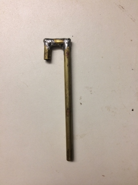
- Pipe with filter holder
- Connecting hose between pump and pipe
Additionally important:
- Flow rate measuring device
Pump:
For the pump, 12V air pumps of the type KOGE KPM27H-12B5, 12V can be used. These have a suction capacity of approximately 1-2 liters per minute with a current of around 200 mA. I used a second-hand 12V air pump, originally intended as a compressor, from Pollin Electronic for €1.50 and was able to modify it slightly for suction operation. Nearly identical new pumps for both suction and pressure operations are also available for around €4-5.
With the small filter diameter of approximately 5 mm (which is reasonable given the detector area), an airflow rate of 0.25–0.5 l/min is already sufficient. Due to the small filter diameter, it is advisable to operate with an airflow rate within this range. The voltage at which the pump achieves the desired airflow rate needs to be determined experimentally, which could be around 6 V. A separate voltage regulator can be used to provide the required supply voltage for the pump from the operating voltage (9–12 V). I used an L7806CV module with a heatsink for this purpose.
If only radon decay products are to be measured, the pump can be operated directly via the power supply (and voltage regulator). For separate measurement of radon and thoron decay products, operation via a relay controlled by the Arduino is required (siehe Seite Impulsmessung, Messwertverarbeitung mit Arduino).
Figure: Brass Pipe for Air Intake
Filter:
The filter should be a fiberglass type that ensures near-surface deposits with a separation efficiency of >95%. I use the MN 85/90 type, which has a separation efficiency of >98%. This type of filter is available from Omnilab for approximately €15 (100 pieces, 25 mm diameter; smaller packaging units are likely not available).
Alternative:
For testing purposes, I once used a filter from a Brigitta No. 2 coffee filter bag. The result was surprising: the effectiveness of the coffee filter was slightly less than half that of the reference material MN 85/90; the exact value was n/n(Ref.) = 0.41. However, the reproducibility of this value was acceptable within the scope of a DIY setup.
For initial measurements, a coffee filter can certainly be used if a correction factor of approximately 2.44 is applied. The additional (relative) uncertainty that should be considered is around 15%, based on my experience. However, I have no experience with other types of filters. For more accurate measurements, it is recommended to use the MN 85/90 filter type.
The filters were punched out from a larger sheet using a 7 mm hole punch. I recommend attaching the filter to the rim of the pipe (the end that will be positioned above the detector) using a thick grease (with a consistency similar to shoe polish; leather grease may also work). This process can be a bit tricky:
- Carefully coat the rim of the pipe with a small but sufficient amount of grease.
- Press the filter lightly onto the rim by hand.
To improve the filter’s adhesion to the pipe’s edge, you can slightly enlarge the outer diameter of the pipe rim with solder.
The component should then be screwed onto the amplifier housing. The filter should be positioned as centrally as possible over the opening of the PIN diode, with a gap of about 1 mm. Finally, connect the pump and the pipe with a suitable tube. The most cost-effective option for the tube is a PVC tube from a hardware store (ensure the tube connection is airtight as well).
Measuring Airflow
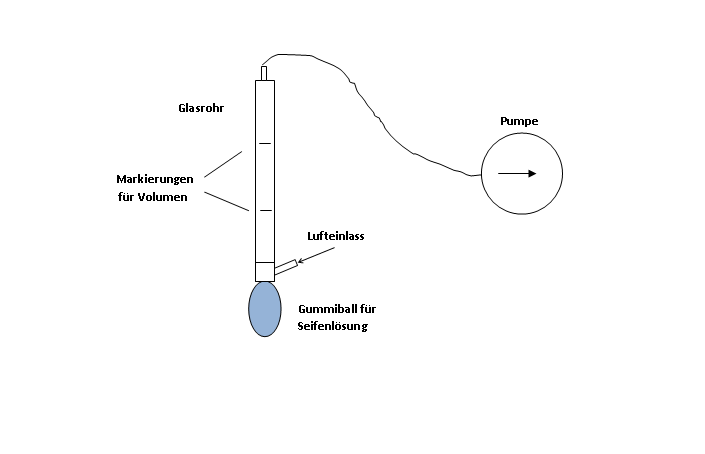
A key requirement for calculating the measurement variable according to Equation (1) is the measurement of airflow. Commercially available airflow meters, whether electronic or floating-body instruments, are not suitable for the intended low-cost solution. Therefore, I suggest a DIY approach using a soap bubble flow meter. Although such devices are also available commercially, they tend to be prohibitively expensive. Here is my proposal for a DIY solution:
Figure: Diagram of a DIY Soap Bubble Flow Meter
Required Materials:
- Glass tube (acrylic or any other transparent material can also be used) with a diameter of 1.5 to 3 cm, approximately 20 cm to 30 cm long
- Copper or brass tube with the same diameter as the glass tube
- Copper or brass tube for air inlet
- Rubber ball or similar for soap solution (I have also used a balloon)
To create the air inlet, I soldered a piece of brass tube, as shown in the figure “DIY Soap Bubble Flow Meter,” into a short piece of copper tube, which was then attached to the glass tube using two-component adhesive.
The diameter of the glass tube should be matched to the airflow rate. Example:
- Airflow rate: 15 l/h = 0.25 l/min
- Diameter of the glass tube: 12 mm
- Distance between the markings: 17.7 cm
- Volume between the markings: 20 cm³
The time it takes for the soap bubble to travel between the markings is 4.8 seconds.
I won’t describe all the details here, but in short, it depends on:
To create an air inlet at the bottom end of the glass tube,
attach a flexible component below this air inlet that allows the soap solution to be lifted by pressing, so that the passing air creates one or more soap bubbles, which are then pushed upwards by the airflow in the glass tube, and
ensure that the time between the two markings can be measured accurately, meaning it should be more than 2 seconds.
The airflow rate Q is determined by the volume between the markings V and the measured time t using the following formula:
Q=V/t wenn V in cm3 und t in Sekunden dann ist Q in l/min àQ=V/t*60/1000
The following figure shows the component I built:
Figure: Flow Meter on the Improvised Tripod
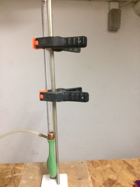
Multiple measurements are definitely recommended (see also Evaluation of Measurements, section on Measurement Uncertainty).
The setup I described is just one example. There are no limits to creativity as long as the above-mentioned criteria are met and the time it takes for a soap bubble to pass through a specific volume can be reliably measured.
Measurement of Pressure Difference
To assess the airtightness of the entire intake system, it is useful to measure the vacuum before the filter. This can be easily done using a U-tube filled with water, as shown in the image. The U-tube can be made from a transparent tube. Details will not be discussed further here.
Figure: DIY U-Tube Manometer
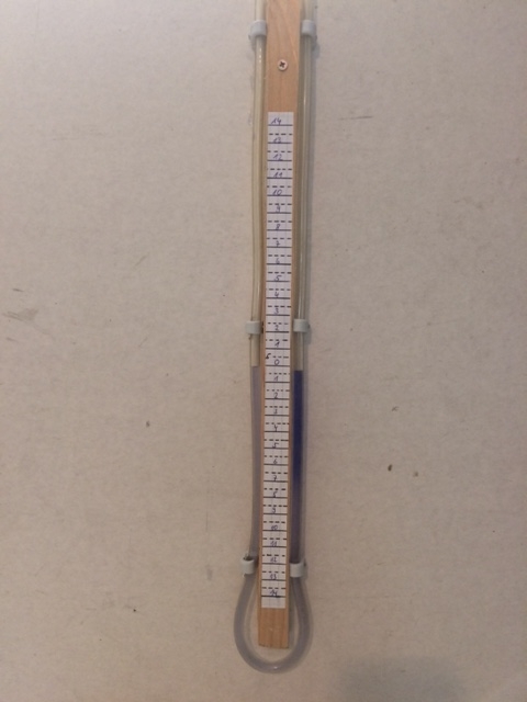
At an airflow rate of 0.25 l/min, I measured a vacuum of 65 mm water column (WC), which corresponds to approximately 650 Pa. For the coffee filter, this value was around 90 mm WC.
These values can serve as a rough guide for assessing the airtightness of the system.
Figure: Installation of the Flow Meter and U-Tube Manometer into the System for Measuring Airflow
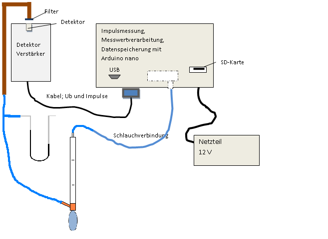
Measuring the airflow is only necessary at the beginning and end of a measurement series. Once sufficient experience has been gained regarding changes in airflow during the measurements, regular measurements can be skipped, and the observed variation range can be taken into account when estimating measurement uncertainty.
